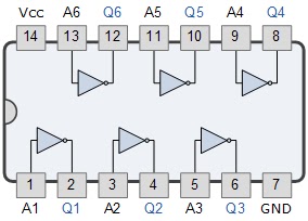
Not Gate Diagram
What is not gate inverter, not logic gate inverter circuit using transistor Logic not gate tutorial with logic not gate truth table Or gate schematic diagram / logic gates and gate or gate truth table
engineering practicals: January 2014
Gate circuit diagram connected explanation power input through circuitdiagram working button circuits then Construction of basic logic gates using nor gate Robot electronics
What is not gate inverter, not logic gate inverter circuit using transistor
Designing not gate using transistorsTransistor gate logic gates digital electronics circuit switch table truth circuits input tutorial off moteino using doorbell base leds implement Not gate circuit diagram and working explanationGate circuit diagram electrical4u principle working ic.
Electrical symbols — logic gate diagramGate diagram logic electrical stencils library vector inverter symbols Learn how to calculate not logic gate valueGate inverter circuit ic 7404 led 74ls04 colour logic hex table truth using two blinking where chaser dual bi transistor.

Not gate
Gate transistors two implementation transistor why electronics electrical lower question need stackLogic gate Handout on circuits and logicImplementation of a not gate with two transistors.
Diagram igem dsd generated reaction visual above based codeSimple "not gate" scheme Engineering practicals: january 2014Shaalaa physics.
-logic-gate-diagram---vector-stencils-library.png--diagram-flowchart-example.png)
Gate gates logic symbol bbc circuit schematic note circuits basic bitesize truth gcse chapter computer science table input handout placed
Xor logic wiring nand xnor nor scosche input vhdl inputs simulate verifyLogic gate circuit xor nand ahirlabs nor xnor Logic gatesGate gates nor using logic circuit diagram basic choose board.
Simple "not gate" schemeNot gate Zitoc nandAnd gate diagram transistor.

Transistor logic inverter circuitspedia
Pin by aman bharti on not gate logic circuitTeam:mit/notgate Or gate schematic diagram / logic gates and gate or gate truth tableWorking of not gate using transistor.
Not logic gateGate truth table logic value learn calculate tutorial Gate using circuit transistors transistor diagram designing circuitdigest proteus simulated software designedGate logic.

Xor logic gate circuit diagram : 1
Study engineering: not gateGate circuit switch switching logic lamp symbol table when glow illustrates open go off Gate signal transistor circuit invert diagram inverter logic ttl arduino electronics robot bjt gates simple ic pinout input level createNot logic gate, diagram.
Gate diagram circuitLogic gates with diagram circuit – ahirlabs Gates circuits digital tutorial output input gate singleGate ic circuit 74ls04 pinout logic diagram gates working chip xnor nor hex input circuitdigest electronic electrical engineering circuits diagrams.

Not gate circuit diagram and working explanation
A simple circuit with a not gateGate logic learnabout Gate diagram practicals engineeringDocument moved.
Circuit gate diagram simpleNot gate: how does it work? (circuit diagram & working principle Circuit diagram gateGate transistor posted administrator december.

What is a not gate?
Logic circuitNot gates tutorial .
.


Handout on Circuits and Logic

Designing NOT Gate using Transistors

NOT Gate - Circuits - Circuit Diagram

engineering practicals: January 2014

Learn How to Calculate NOT Logic Gate Value - Tutorial, Definition